SMART Response XE terminal schematic
Note: une version française est disponible plus bas dans la page
Some comments
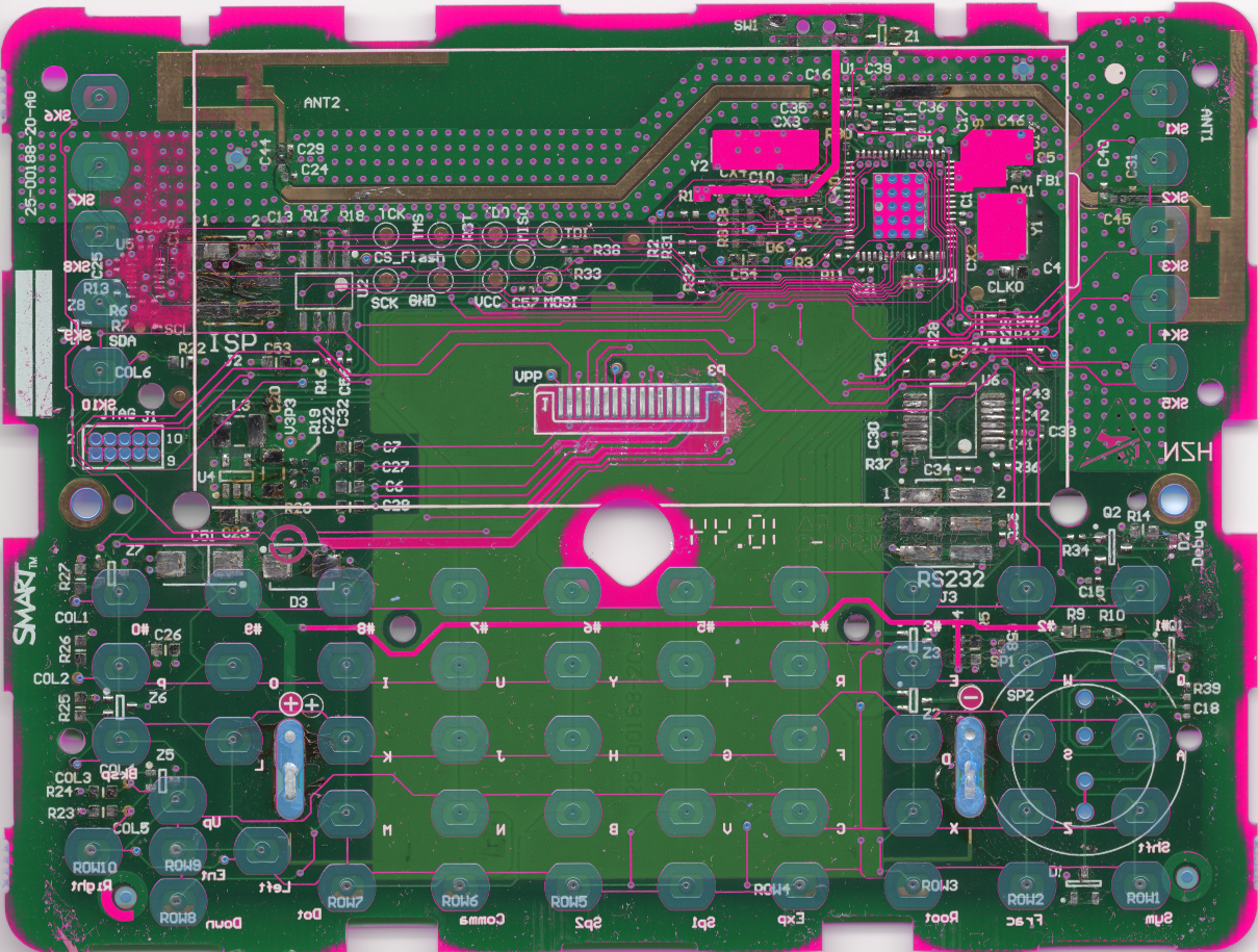
- As a lazy person, I first asked SMART Technologies if they can release the schematics to the DIY community. As they refused to make the schematics available, I did reverse engineering from an HD scan found on Hackaday.io I also used one of the terminal I own.
- The schematic is not 100% accurate and there are probably some errors and/or missing parts
- Components which value is ending with a * are not mounted
- The decoupling capacitors are not represented
- MAX3226 is a guess. I have looked at different RS232 transceivers and it is the one that matches best.
- There is one mystery components (U5) I was unable to discover what it is. It has an I²C interface and a digital I/O.
What can easily be added
LED
There is provision for an LED (identified as DEBUG on the PCB).
The LED is driven by PB0
One just needs to add 2 resistors (R34, R14), a NPN (Q2) and a LED.
Q2 can be a 2N2222
R34 a 4,7K resistor and R14 a 220 Ohms resistor
BUZZER
There is also provision for a buzzer.
The buzzer is driven by PE3
The schematic seems somewhat convoluted but it allows several configurations.
Direct drive with I/O
Mounting R39 0 Ohm, a small piezo buzzer and R10 100 Ohms you have the cheaper version. R10 can be modified to get a more or less loud sound
Transistor buffered and speaker
Mounting Q1 and R9 you can use a small speaker.
Quelques remarques
- Comme je suis un peu flemmard, j\'ai d\'abord demandé à SMART Technologies s\'il pouvait donner les schéma à la communauté DIY. Comme ils ont refusé, j\'ai refait les schémas à partir d\'un scan HD trouvé sur Hackaday.io J\'ai aussi utilisé l\'un des terminaux que je possède.
- Les schémas ne sont pas fidèles à 100% et il y a probablement des erreurs ou omissions
- Les composant dont la référence se termine par * sont non montés
- Les condensateurs de découplage ne sont pas représentés
- Le MAX3226 est une supposition. J'ai regardé plusieurs interfaces RS232 et c'est celui qui correspondait le mieux.
- Il reste un composant mystère (U5) je n\'ai pas trouvé ce que c\'est. il a un bus I²C est une interface digitale.
Ce que l\'on peut facilement ajouter
LED
Il y a une zone prévu pour monter une LED (identifié par DEBUG sur le circuit imprimé).
La LED est pilotées par la sortie PB0
Il suffit d\'ajouter 2 résistances, un transistor NPN et une LED.
Q2 peut être un 2N2222
R34 une résistance de 4,7K and R14 une résistance de 220 Ohms.
BUZZER
Il y a aussi un emplacement prévue pour monter un buzzer.
Le buzzer est piloté par la sortie PE3
Le schéma semble un peu tordu mais il permet plusieurs configurations.
Pilotage direct par un I/O
On monte R39 0 Ohm, un petit buzzer piezo et R10 100 Ohms pour la version économique. La valeur de R10 peut être modifiée pour adapter le niveau sonore.
Transistor + haut-parleur
En montant Q1 et R9, on peut utiliser un petit haut-parleur.